OML
The afem.oml package provides a minimal set of entities and tools intended
to make defining structural components easier and more efficient. Many of the
tools used to create parts require a solid defining the common material of
the part given its basis shape. Some tools are more automated and parametric
and therefore need more information, like a reference surface or curve. The
oml package, and more specifically the Body class, are intended
to provide a single type that contains all necessary information. The entities
and tools can be imported by:
from afem.oml import *
The intent of the oml package and the Body class is best
understood by manually building a solid shape that represents a basic wing as
shown in the following example:
from math import tan, radians

from afem.geometry import *
from afem.graphics import Viewer
from afem.oml import *
from afem.sketch import *
from afem.topology import *

# Parameters
semispan = 107.  # wing semi-span
sweep = 34.  # Leading edge sweep
uk = 0.28  # Percent semi-span to locate section cross section
c1 = 51.5  # Root chord
c2 = 31.  # Chord of second section
c3 = 7.  # Tip chord
t3 = 3.  # Tip washout in degrees

# Define leading edge points of cross sections
p1x, p1y = 0., 0.
p2x = semispan * uk * tan(radians(sweep))
p2y = semispan * uk
p3x = semispan * tan(radians(sweep))
p3y = semispan

# Create a cross section using an UIUC airfoil file
cs = Airfoil()
cs.read_uiuc('../models/clarky.dat')

# Define cross section planes
pln1 = PlaneByAxes((p1x, p1y, 0), axes='xz').plane
pln2 = PlaneByAxes((p2x, p2y, 0), axes='xz').plane
pln3 = PlaneByAxes((p3x, p3y, 0), axes='xz').plane

# Build cross sections
cs.build(pln1, scale=c1)
wire1 = cs.wires[0]
cs.build(pln2, scale=c2)
wire2 = cs.wires[0]
cs.build(pln3, scale=c3, rotate=t3)
wire3 = cs.wires[0]

# Loft a solid
shape = LoftShape([wire1, wire2, wire3], True, make_ruled=True).shape

# Make a body
wing = Body(shape, 'Wing')
wing.set_transparency(0.5)
wing.set_color(1, 0, 0)

# Build a reference surface using chord lines of the cross sections. Make sure
# to use the same scaling and rotation parameters. Set the parametric domains
# to be between 0 and 1 for convenience.
chord1 = cs.build_chord(pln1, scale=c1)
chord2 = cs.build_chord(pln2, scale=c2)
chord3 = cs.build_chord(pln3, scale=c3, rotate=t3)
sref = NurbsSurfaceByInterp([chord1, chord2, chord3], 1).surface
sref.set_udomain(0., 1.)
sref.set_vdomain(0., 1.)

# Set the wing reference surface
wing.set_sref(sref)

# Show wing and reference surface
gui = Viewer()
gui.add(wing, wing.sref)
gui.start()

# Show the underlying shape of the reference surface
gui.clear()
gui.add(wing.sref_shape)
gui.start()

# Evaluate point
p = wing.eval(0.5, 0.5)

# Extract a plane
pln = wing.extract_plane(0.5, 0., 0.5, 0.5)
face = FaceByPlane(pln, -10, 10, -10, 10).face

# Extract a trimmed curve
crv = wing.extract_curve(0.15, 0.05, 0.15, 0.95)

gui.clear()
gui.add(wing.sref, p, face, crv)
gui.start()
After the necessary modules are imported, a few parameters are specified that will be used to define the shape of the wing:
semispan = 107.  # wing semi-span
sweep = 34.  # Leading edge sweep
uk = 0.28  # Percent semi-span to locate section cross section
c1 = 51.5  # Root chord
c2 = 31.  # Chord of second section
c3 = 7.  # Tip chord
t3 = 3.  # Tip washout in degrees
The wing will be defined by three cross sections using the same airfoil but at different locations and scales. A constant leading edge sweep is assumed so the leading edge locations of each cross section are:
p1x, p1y = 0., 0.
p2x = semispan * uk * tan(radians(sweep))
p2y = semispan * uk
p3x = semispan * tan(radians(sweep))
p3y = semispan
An airfoil from the UIUC airfoil database is used to create the cross section:
cs = Airfoil()
cs.read_uiuc('../models/clarky.dat')
One advantage of using an Airfoil is that the leading and trailing
edge points are stored and from that a chord line can be built which later will
be used to build additional reference geometry stored with the wing.
Three planes are defined using the points derived from the wing parameters:
pln1 = PlaneByAxes((p1x, p1y, 0), axes='xz').plane
pln2 = PlaneByAxes((p2x, p2y, 0), axes='xz').plane
pln3 = PlaneByAxes((p3x, p3y, 0), axes='xz').plane
These planes represent the eventual location of the 3-D airfoil cross sections where the local origin of the plane is also the leading edge in this case. At each section, a 3-D wire is built by providing the 3-D plane and a scaling and rotation parameter:
cs.build(pln1, scale=c1)
wire1 = cs.wires[0]
cs.build(pln2, scale=c2)
wire2 = cs.wires[0]
cs.build(pln3, scale=c3, rotate=t3)
wire3 = cs.wires[0]
These wires are then used to loft a solid shape:
shape = LoftShape([wire1, wire2, wire3], True, make_ruled=True).shape
The make_ruled=True option was used to produce linear segments between the
airfoil cross sections, rather than blending them together with approximation.
At this point, a solid body (i.e., a Solid) has been defined and a
Body can be initialized:
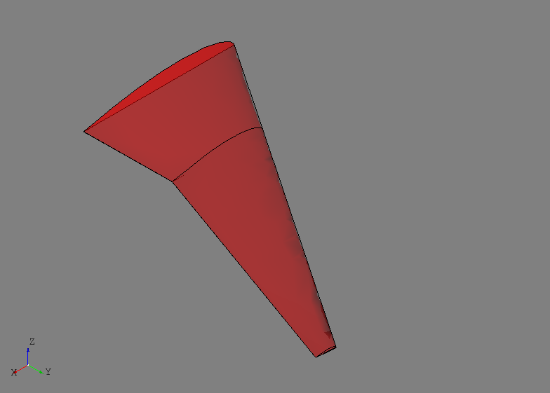
wing = Body(shape, 'Wing')
The name parameter, given as “Wing” in this example, is optional but is
useful and can be treated as a default type of metadata. Defining a valid
Solid is the only hard requirement when defining a Body for
use during structural modeling. The user can use all the tools available to
create them manually as done above, or they can be derived by importing data
from other sources such as STEP files. The wing derived above is shown below:
It is at times convenient to define structural components using normalized or
relative parameters rather than in absolute terms. For example, in a wing it is
common to define a spar’s location and orientation by percent chord and percent
semispan. This leads to the need for some kind of “reference geometry” on which
to evaluate these types of parameters. For a wing, a natural solution is to
define a continuous surface that generally represents its planform shape. Since
many of the structural modeling tools use this type of surface, storing a
“reference surface” and other reference geometry is provided by the
Body class.
For the wing shown above, a reference surface will be built by lofting the chord lines of the three airfoil cross sections:
chord1 = cs.build_chord(pln1, scale=c1)
chord2 = cs.build_chord(pln2, scale=c2)
chord3 = cs.build_chord(pln3, scale=c3, rotate=t3)
sref = NurbsSurfaceByInterp([chord1, chord2, chord3], 1).surface
sref.set_udomain(0., 1.)
sref.set_vdomain(0., 1.)
The chord lines are built using the same scaling and rotation parameters and a linear surface is constructed. The parametric domain of the surface is set to be between 0 and 1 for convenience. This essentially corresponds to the u-direction being percent chord and the v-direction percent semispan (in this case along the sweep direction). The surface is set as the reference surface by:
wing.set_sref(sref)
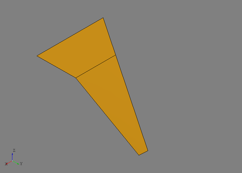
When a reference surface is set, the method will automatically construct an
underlying shape by splitting the surface at any C1 discontinuities. This shape
is primarily used for intersection methods when extracting curves since C1
discontinuous surfaces may be numerically unreliable, but it is provided to the
user if needed. This wing.sref_shape is shown below:
A number of methods are provided for convenience if the Body contains reference geometry such as as reference surface. A point on the surface can be evaluated by:
p = wing.eval(0.5, 0.5)
A plane can be defined between two points using the reference surface:
pln = wing.extract_plane(0.5, 0., 0.5, 0.5)
Here, two points are defined and then a third is defined by translating the first point in the direction of the reference surface normal. These three points are used to define a plane which can be useful for structural modeling.
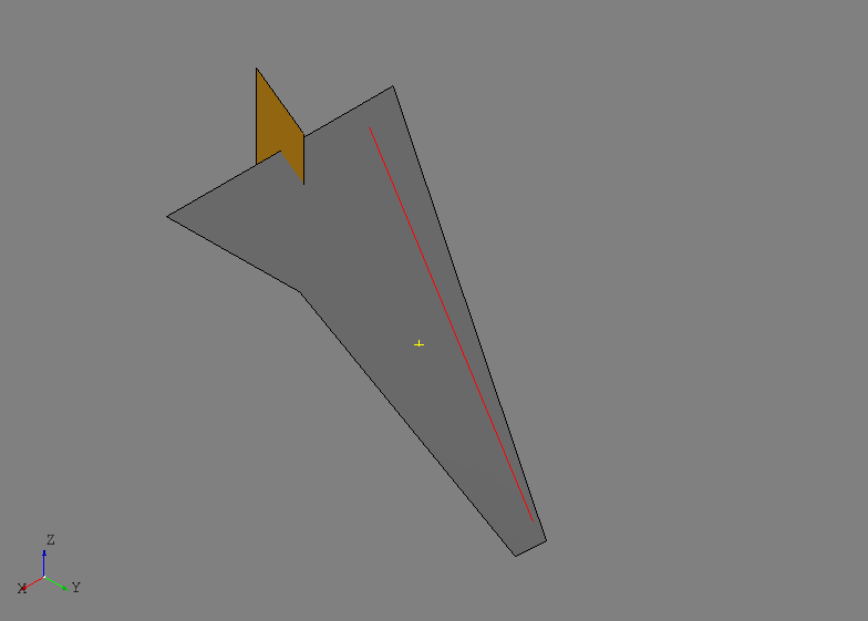
Sometimes it may be useful to build a curve within the reference surface between two points as shown below:
crv = wing.extract_curve(0.15, 0.05, 0.15, 0.95)
This method will generated a TrimmedCurve between the parameters by
intersecting a basis_shape with the reference surface. If a basis shape is
not provided, a plane will be constructed as described above. The result of
these methods are shown below:
The main takeaway for the oml package and the Body class is that
it is meant to be a container for minimum data needed for structural modeling
with minimal restrictions and assumptions. Creating the solid contained by the
Body, as well as any associated reference geometry, can be as complex
or as simple as the user needs and/or desires.
Entities
Body
-
class
afem.oml.entities.Body(shape, name='Body')¶ Generic class for solid bodies and encapsulating necessary information when creating structural components.
- Parameters
shape (afem.topology.entities.Solid or afem.topology.entities.Shape) – The shape which should be a solid.
name (str) – The name.