Sketch
The afem.sketch package provides basic entities and tools for the creation
of 2-D planar geometry. This is not a constraint-solving sketch module
like ones found in most CAD systems, but rather a simplified way to define
planar 2-D curves and convert them to 3-D for operations like lofting or
extrusion. The entities and tools can be imported by:
from afem.sketch import *
The general process to use the sketch package is to define a reference
plane in 3-D space, use that plane to define 2-D geometry, and then convert
that 2-D geometry into 3-D space. The example below demonstrates this process:
from afem.geometry import *
from afem.graphics import Viewer
from afem.sketch import *
from afem.topology import *

# Create a new cross section
cs = Airfoil()

# Generate a 2-D profile by reading and approximating an airfoil file from
# the UIUC database. Close the trailing edge if necessary.
cs.read_uiuc('../models/clarky.dat', close=True)

# Define a plane at the root and scale
pln1 = PlaneByAxes(axes='xz').plane
cs.build(pln1, scale=5)
wire1 = cs.wires[0]

# Define plane at the tip and rotate
pln2 = PlaneByAxes((3, 15, 0), axes='xz').plane
cs.build(pln2, scale=1.5, rotate=3)
wire2 = cs.wires[0]

# Use the wires to loft a solid
shape = LoftShape([wire1, wire2], True).shape

gui = Viewer()
gui.add(wire1, wire2, shape)
gui.start()
The sketch entities and tools are imported by:
from afem.geometry import *
from afem.graphics import Viewer
from afem.sketch import *
from afem.topology import *
A special type of CrossSection will be used to generate a section
from an airfoil file:
cs = Airfoil()
where cs uses the xy-plane by default since no plane was provided. This
default reference plane is the one used when defining 2-D geometry. The plane’s
origin corresponds to the (0, 0) location of the local coordinate system.
In this example, a 2-D curve is generated by reading an airfoil file from the UIUC database:
cs.read_uiuc('../models/clarky.dat', close=True)
The option close=True is used to close the trailing edge of the airfoil if
it is open (i.e., the points are not coincident). This methods uses 2-D
approximation to fit the airfoil points.
The 2-D profile can now be converted to 3-D space by providing a new 3-D plane
in the build method:
pln1 = PlaneByAxes(axes='xz').plane
cs.build(pln1, scale=5)
wire1 = cs.wires[0]
Note that the new plane can be oriented in any way, but the 2-D geometry will
be relative to the plane’s origin and local axes. The build method accepts
a global scaling and rotation parameter which is relative to the plane’s
origin. When the cross section is built, 3-D topology will be available
for use. Another section is built using a different reference plane as well as
different scaling and rotation parameters:
pln2 = PlaneByAxes((3, 15, 0), axes='xz').plane
cs.build(pln2, scale=1.5, rotate=3)
wire2 = cs.wires[0]
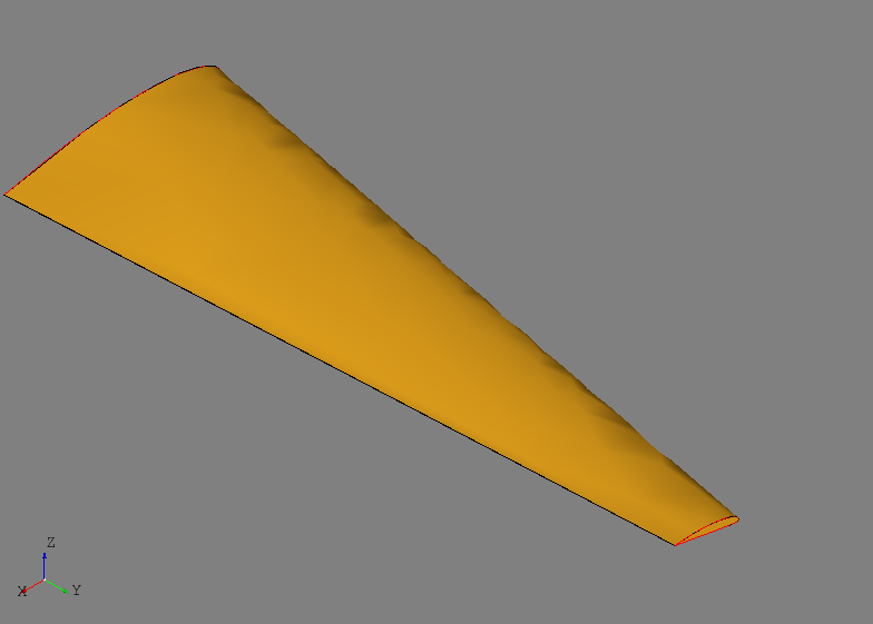
Note that the same 2-D profile is used to generate different 3-D shapes. The two wires created by this process are closed and used to generate a lofted solid:
shape = LoftShape([wire1, wire2], True).shape
The results can be visualized using the viewing tool and should look like the wing shape shown below:
gui = Viewer()
gui.add(wire1, wire2, shape)
gui.start()